To obtain high quality data in radiation detection and measurement systems, many factors must be considered. These include selection of appropriate detectors, front end and signal processing electronics.
The next factor that can have a significant effect on the success of the measurement is proper system integration. Improper system integration can result in failure to achieve a desired result even with the finest components available.
Design and integration of complete systems involves decisions such as the physical placement of the components in the facility or vehicle and EMI suppression methods. Many programs have ended in failure due to poor system design and the EMI problems that followed. Proper attention must be given to all aspects of detector systems.
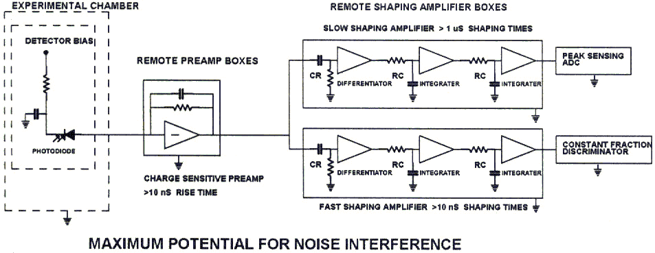
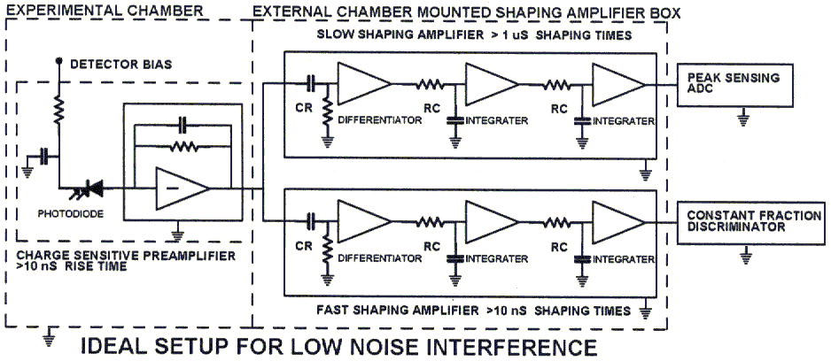
The diagrams that follow show two contrasting detector and amplifier
configurations. The first is doomed to suffer poor performance.
The second has an inherent probability of high performance.

There are two problems with a system with distance between the individual
components. Every cable extension between components results in a
increase in noise. Electronic noise from the charge preamp increases
due to an increase in the input terminal capacitance. Also, EMI induced
in every cable segment due to the loop antenna formed between the grounded
components. The ideal coaxial cable completely shields the inner
conductor, but most reasonably priced cable is not ideal.

The system shown above is close to ideal for several reasons. Inherent resistance to EMI is the one of the most notable features. Notice that the detector, preamp, shaping amplifiers and interconnecting cables are completely shielded by the single chamber and electronics box network. There is little potential for inducing EMI. In this system the only EMI potential is in the shaping amplifier output cable loop antenna. However this is a high level signal so it is the least sensitive node. Noise from this source is easy to reduce. The simple low cost method is to simply loop the signal cable about five turns (more turns don't help much) on a high permeability material toroid core, forming a low pass filter. I recommend cores with maximum inductance per turn such as the W-42915-TC from Magnetics Inc. (http://www.mag-inc.com/). Note that this does not alter the signal in any way other than reducing the noise pickup. The effect of all this is to break the noise current loops. Using this technique can also help reduce loop current noise on preamp, PM tube anode and other detector output cables when extension cables must be used.
The most expensive method is to use coaxial cables with secondary shields constructed with high mu metal foils (sometimes called Darsbury cable). However this doesn’t offer any greater performance than low cost 50 Ohm cable with a proper toroid treatment.
The last things that will reduce the possibility of EMI is to low pass filter the bias for the detector and pre-amp. This is best installed just inside the box wall. A simple RC (10 Meg. Ohm and .01 uF) is fine for the detector bias and a LC filter (>100 uH and > 10 uF) is a good idea for pre-amp power.